top of page
introduction
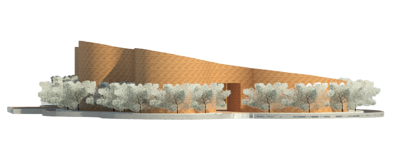
This project involves the production of Revit model of the selected architecture design using Architectural Components such as Wall, Roof, Stairs, Floor, Curtain Wall, Doors and Windows. At the end of the project, the model shall be used to generate documentation drawings, using Revit Architecture’s Documentation Components such as Sheets, Titleblock, Sections, Room Tags, Schedule & etc.
PROGRESS
Progress 01
.png)
01
Detail Line
Before developing my idea, I start planning the shape by using detail lines in order to get the perfect shape with the correct dimensions that I wanted.
Planning of shape
.png)
02
Dimensions
I've tried several times to get the shape done because it's hard to get the correct angle and shape due to it's organic form. After i've done with it, I start putting the walls along the detail line to create the floor plan.
Start shaping
_edited.jpg)
03
Floor Plan
First floor plan was created with the appropriate dimensions which helps me on further developing my idea.
First Floor Plan
_edited.jpg)
04
Floor Plans - Ground Floor
I've added trees and also water features at the surrounding of the building to achieve a better result and the overall appearance of the floor plan.
Ground Floor Plan
_edited.jpg)
05
Floor Plans - First Floor
After finishing the ground floor, I started doing the first floor plan. Underlay of ground floor wasn't close as I can constantly check on what's missing.
First Floor Plan
Progress 02
_edited.jpg)
_edited.jpg)
01
Height of Walls
I've used the basic roof in order to help me to create a sloping height of the wall. Due to the reasons where my building was designed to have different height on both sides, I've also used the reference plan to create a slop and attach the wall to it.
Accurate Wall Height
_edited.jpg)
02
Entrance
For the entrance gateway, I used the edit profile to get the curvy shape that I wanted for the top and duplicate it for the second gateway and accordingly.
Gateway
_edited.jpg)
03
Entrance Wall Cut
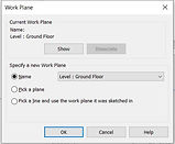
Since my building uses curve walls, it is hard to edit the shape that I want it to be, I then discover that I can use model in place method to get the shape that I want in order to match the height of the gateway.
Entrance Wall
STEPS
_edited.jpg)
_edited.jpg)
.png)
-
Model In Place
-
Generic Model
-
Component
-
Reference Plan
_edited.jpg)
.png)
_edited.jpg)
_edited.jpg)
04
Divider
The same steps was used to create the separation outside of the gallery as I wasn't sure about what are the other method that can be use.
Divider Partition
Progress 03
01
Roof
I uses the generic floor to create the sloping effect of my 'green roof' as the basic roof does not allowed me to do the slopping effect for an organic building with curve walls. I placed floor from the floor plan and uses the modify sub elements to pull each of the boundary line to achieve the perfect slop.
Sloping Roof
_edited.jpg)
-
STEPS
_edited.jpg)
_edited.jpg)
.png)
.png)
02
Water Feature
After finishing the roof, I start modify the water feature which was located at the surrounding of the structure. I uses create floor method and apply 'water' as a material onto it. For the side of the water feature, I uses the create wall method and set the top constraint to the amount that I wanted to prevent the water from flowing out.
Water Feature
.png)
-
STEPS
_edited.jpg)
_edited.jpg)
.png)
_edited.jpg)
_edited.jpg)
03
Trees
I've tried applying a lot of trees in order to find the most suitable tree for the site and also the building. I've chosen two different types of tree to place into the building.
Trees
_edited.jpg)
-
STEPS
_edited.jpg)
First, click on the massing & site and choose the site component and look at the properties where varieties of trees will be shown here.
_edited.jpg)
_edited.jpg)
04
Open Amphitheater
Previously, I uses the floor to create the different height for the seats of the amphitheater as I wasn't sure what component should I be using. I tried redoing the open amphitheater seats again after figuring out how to make it better.
Amphitheater
-
STEPS
_edited.jpg)
_edited.jpg)
I begin with creating a wall and click on the component (Model In-Place) to select floor from the list.
_edited.jpg)
_edited.jpg)
_edited.jpg)
Then, I chooses revolve from the create tools and proceed with setting a reference plan by clicking 'pick a plane'.
_edited.jpg)
_edited.jpg)
Hide the wall.
Write the angle for the seats from the properties tab.
_edited.jpg)
_edited.jpg)
Next, I were to create the size and shape of the amphitheater that I wanted.
04
Columns
After putting the detail lines on every corner, I start to insert the column on the corner based on the detail line instead of using gridline. After inserting columns, I've checked the top and also base constraint to prevent it from exceeding the boundary.
Structural Column
_edited.jpg)
Progress 04
REVIT FAMILY CREATION
01
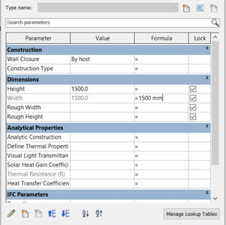
Circular Window
I've did a circular window family as it is more suitable for my organic structure.
Window
02
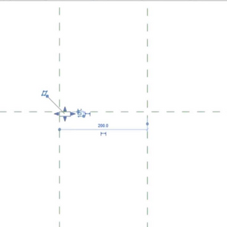
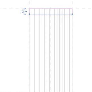
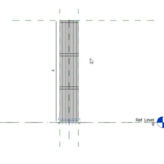
Parametric Window with Louvers
I've did a louvre window on the exterior of the cafe as it can be twice as wide as standard windows while letting the users to control the amount of breeze that are needed.
Window
FIRST REVIT OUTCOME
Progress 06
DOCUMENTATION
_edited.jpg)
01
Floor Plan
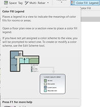
Before placing it on the documentation template, I create room for all the spaces and also proceed to create room schedule for all the rooms. After having room schedule, I then uses the colour fill legend to add colour to every spaces.
Colourful Floor Plan
-
STEPS
_edited.jpg)
_edited.jpg)
_edited.jpg)
_edited.jpg)
_edited.jpg)
_edited.jpg)
02
First Floor Plan
The same method were used to create the first floor plan in order to get a better looking.
Colourful Floor Plan
-
STEPS
_edited.jpg)
03
Roof Plan
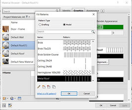
The roof plan was created by using the site plan and I added the pattern on the roof in order to get the 'roof look'. Then I uses masking region to create the arrow to indicate that the roof slopped upwards.
Roof Plan
_edited.jpg)
_edited.jpg)
_edited.jpg)
_edited.jpg)
_edited.jpg)
04
Elevations
To create the elevations, I placed the grid line on the columns manually because I wasn't allow to use the same grid line as the one I created at the floor plan due the curvy and organic shape.
Elevations
_edited.jpg)
North Elevations
_edited.jpg)
East Elevations
_edited.jpg)
South Elevations
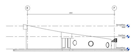_edited.jpg)
West Elevations
05
Sections
To create the sections, I choose the two most interesting place and cut it through. After selecting the sections, I then uses masking region to cut profile. After finish cut profile, I callout two parts.
Sections
Callouts
.png)
Sections 1
.png)
Sections 2
_edited.jpg)
Callout 1
_edited.jpg)
Callout 2
06
Exploded Axonometric
To create exploded axonometric, I start with clicking the components accordingly and pull them up one by one.
Exploded Axonometric
-
STEPS
.png)
_edited_edited.jpg)
_edited.jpg)
_edited.jpg)
_edited.jpg)
Progress 06
DOCUMENTATION
01
Documentation Drawings
To complete the project documentation task, I have to load in the template into the project in order to place the document inside the sheets.
Documentation
-
STEPS
_edited.jpg)
From the project browser, find 'sheets' from the list, right click and select new sheets.
From the titleblock, choose the template that were downloaded beforehand from Times and use it for inserting the documents.
_edited.jpg)
Completed Documentation Drawings
_edited_edited_edite.jpg)
cyn
whatever good things we build end up building us...
bottom of page


